Main lubricating-oil transfer · vertical intake · immersed shaft assemblies
Jiangsu Huadian Machinery Manufacturing Co., Ltd.
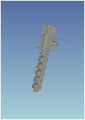
Jiangsu Huadian’s reviewed pump directions connect hydraulic selection with the structure below the mounting plane. HCL addresses main lubricating-oil transfer, HLY uses a submerged impeller in a vertical long-shaft arrangement, and HFY puts a supported shaft and liquid end inside the vessel or sump. For a buyer, the useful distinction is how the liquid, shaft supports, material schedule and removal route fit the installation—not simply whether the pump is called vertical.
- Chinese legal name
- 江苏华电机械制造有限公司
- Published location
- Jingjiang, Jiangsu
- Reviewed directions
- HCL · HLY · HFY
- Existing model
- HCL100-12.5*3
Choose the direction around the liquid and mounting arrangement
Huadian lists additional chemical, multistage, self-priming and wastewater equipment. These do not make one reviewed HCL selection suitable for every process. Establish the actual liquid and installation drawing before choosing a family, and keep each family’s curve and material schedule with its own offer.
| Your requirement | Documented direction | Information that changes the selection |
|---|---|---|
| Main lubricating-oil circulation or transfer | HCL main lubricating-oil pump | Oil grade/viscosity and temperature, duty range, suction conditions, electrical frequency and acceptance basis. |
| Water intake or drainage through a vertical long-shaft assembly | HLY submerged-impeller arrangement | Liquid levels, intake geometry, shaft length and the component material class. |
| An immersed liquid end for neutral/corrosive process liquid | HFY / HFYW long-shaft immersion | Liquid/solids, mounting depth, shaft supports, cooling/service arrangement and lifting access. |
HCL100-12.5*3: select the oil duty against one identifiable table row
The official parameter tab contains an identifiable HCL100-12.5*3 row. Other rows use HLS labels despite the HCL page heading; they are not merged into this existing model.
The overview identifies marine main lubricating-oil transfer and general industrial lubrication as application directions. Provide the oil specification, viscosity over startup/normal operation, density, temperature and any entrained gas or contamination. Ask which hydraulic and motor selection is offered for those conditions, rather than treating a water-based catalogue point as the complete lubrication duty.
The parameter text distinguishes 380 V / 50 Hz and 440 V / 60 Hz speed alternatives. Keep the selected 1,450 r/min row separate from the 60 Hz offer. The same page has malformed general temperature and pressure statements; no operating limit is inferred from them. Obtain the permitted liquid temperature, pressure and seal conditions in the selected supply documentation.
| Field | Published row | Order significance |
|---|---|---|
| Flow range / head | 100–120 m³/h / 36 m | Request the selected curve and its test-liquid basis. |
| Motor / speed | 30 kW / 1,450 r/min | Confirm motor loading for the actual oil and the offered electrical supply. |
| Efficiency | 79.2% | Listed-row value; it is not a measured efficiency for your installed oil system. |
View the reviewed product family →
Resolve the whole component schedule
The HCL material table gives several configuration levels and distinguishes guide body, impeller, shaft, shaft sleeve, seals and bearings. A stainless impeller does not establish that the complete assembly is stainless. Agree each liquid-contact part and the fitted bearing/seal references.
HLY: a seawater label is not a complete material specification
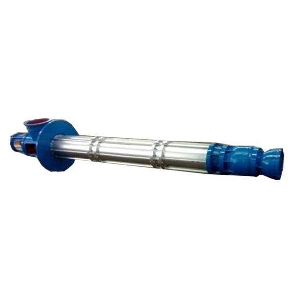
The HLY source describes a vertical installation with a submerged impeller for intake and drainage. Its material chart separates water intake, urban/industrial drainage, corrosive industrial discharge and seawater directions. These classes change several components independently.
For example, the chart keeps HT250 outlet/base components in several classes while changing the outer pipe, guide components, impeller, shaft and sleeve for the corrosion-related directions. Use the complete selected bill of materials. State chloride/chemical content, solids and the intended operating temperature, and request compatibility confirmation for the actual stream.
Dimension the mounting plane, suction-end location, normal/minimum/maximum levels, intake clearance and discharge pipe connection. Include the shaft/column length and the space required to lift the assembly. The page’s general head-range unit is malformed, so use a selected hydraulic curve rather than repairing the printed unit by assumption.
HFY: shaft support and cooling access are part of the tank design
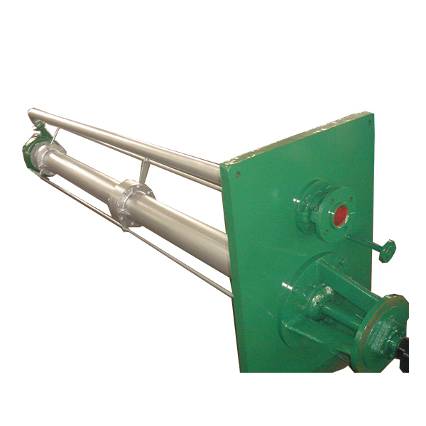
The HFY sectional drawing identifies sliding bearing sleeves, intermediate bearing supports, shaft couplings, a cooling pipe and a separate discharge path. Those details explain why the required immersion depth cannot be specified without the support and service arrangement.
Send the liquid composition, solids/debris, temperature, density and vessel dimensions. Ask for the selected shaft sections, support positions, bearing materials, cooling or lubrication service requirements and removal procedure. Show the mounting loads, discharge piping and lifting clearance on the same drawing.
The manufacturer describes a 1,450 r/min direction and an HFYW derivative for non-clogging duties. Specify the selected impeller and passage for actual solids rather than assuming the derivative’s scope applies to every HFY. Broad life, maximum-depth and API statements in the overview are not used as order guarantees; any required standard, edition and test scope must be agreed for the supplied assembly.
Approve the installed geometry
Define the mounting plane, shaft/column length, liquid-end clearance, support locations and discharge interface.
Agree services and wear parts
Identify cooling/lubrication requirements, bearing sleeves, shaft connections and seals with replacement references.
Plan removal before installation
Check lifting height, lifting points, pipe disconnection and access to supported shaft sections.
Use a historical test record to frame today’s acceptance request
The company profile describes design, testing and pump manufacturing activities. Its undated personnel and annual-output statements are not treated as confirmed present capacity. Ask about the facilities and test arrangement assigned to the actual order.
An Equipment Industry Development Center publication dated 8 April 2018 lists 江苏华电机械制造有限公司 and HFY100-37 submerged pumps among the historical sampling results. The identified June 2017 samples, 1706066 and 1706067, are recorded as passing, with the named Liaoning testing centre. This is evidence about those model/batches, not current certification of every Huadian pump or a test of HCL100-12.5*3.
For the order, agree the selected curve, test liquid, duty points and tolerances, motor/electrical identification and dimensional checks. For oil service, clarify the basis for performance and power selection. For a long-shaft assembly, include shaft alignment/support and installation records in the handover scope.
Make the supply boundary explicit
Confirm the legal supplier, supplied motor/coupling/base or mounting plate, service piping, documentation, installation responsibilities and spare-parts package. Match acceptance records to the selected model and the supplied serial identification.
Build the brief around your lubrication circuit or tank
Liquid and operation
- Oil grade/viscosity and startup/normal temperatures, or process chemistry/solids and corrosion conditions.
- Normal/minimum/maximum flow, required head, inlet conditions and operating sequence.
- Motor voltage/frequency and the actual duty used for motor and hydraulic selection.
Vertical geometry and materials
- Mounting plane, minimum/normal/maximum liquid levels, immersion length and bottom clearance.
- Intake/discharge layout, shaft supports, cooling/lubrication availability and removal space.
- Complete component material schedule, selected seals/bearings and replacement references.
Acceptance and delivery
- Selected curve, agreed test basis/tolerances, drawings and identification records.
- Any required project standard with edition/scope and the applicable supplied documentation.
- Quantity, destination, requested date, installation responsibilities and maintenance/spares.
Submit through KanBeng’s enquiry form with this factory named in your request.