
Separate chemical transfer from the evaporator circulation loop
Jingjiang Yonglong Pump Co., Ltd.
Yonglong’s useful catalogue distinction is between generating transfer head and circulating a large volume through a process loop. IH and IHF address chemical transfer; SPP and FJX address different high-volume circulation arrangements. Compare the actual speed, liquid density, seal and installation before requesting a pump-and-drive quotation.
- Site identity
- 靖江永隆泵业有限公司
- Listed base
- Xinqiao, Jingjiang, Jiangsu
- Existing catalogue entries
- IH · IHF · SPP · FJX
- Selection distinction
- Transfer head · circulation resistance
A process-pump catalogue is broader than a pump selection
The company introduction and contact page identify Yonglong in Jingjiang’s Xinqiao industrial area. The catalogue contains chemical centrifugal, self-priming, submerged, magnetic-drive, slurry, screw and evaporation-circulation directions. The four existing public entries here cover IH, IHF, SPP and FJX. They retain separate duties; a curve from one family should not be used to select another.
For a chemical plant, specify which part of the process the pump serves: transferring feed between vessels, keeping an evaporator loop moving, handling a slurry from a tank, or containing a hazardous liquid. Ask for the selected pump, driver, seal auxiliaries and support arrangement as one defined assembly. A product photograph establishes the catalogue configuration shown, not the contents or lead time of a current quotation.
The site heading uses 靖江永隆泵业有限公司, while some original photographs and a footer include 靖江市永隆泵业有限公司. Keep the exact contracting identity consistent across the quotation, licence and test documents. This catalogue review does not establish an independently audited plant, patent ownership or a current third-party certificate.
Transfer pressure and process circulation solve different problems
An acid-transfer enquiry normally starts with the source and receiving vessels, required delivery and connecting pipework. An evaporation enquiry also needs the recirculation rate, heat exchanger and loop resistance, operating pressure and liquid condition near boiling. A high-volume circulation family does not supply the same selection envelope as the IH chemical-transfer entry.
Use the following distinctions to decide which documentation to request. Chemical compatibility remains a separate decision for every direction: the published application lists do not approve every concentration, temperature, solid content or mixture.
| Process task | Yonglong direction | Selection evidence to request |
|---|---|---|
| Chemical feed or vessel transfer | IH metal wet end / IHF lined wet end | Actual flow/head, speed, materials and seal arrangement |
| Large-volume horizontal circulation | SPP mixed-flow, rear-withdrawal construction | Complete model plus impeller letter, density and drive schedule |
| Evaporation / concentration loop | FJX forced circulation | Loop resistance, hot-liquid suction, supports and seal auxiliaries |
| Abrasive liquid from a tank | UHB or LJYA catalogue direction | Particle distribution, concentration basis and wear construction |
| Hazardous-liquid containment | CQF magnetic-drive catalogue direction | Confirmed exact model, temperature and bearing/protection instructions |
An IHF model name alone does not fix the duty point
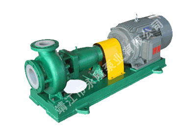
IHF is described as a single-stage, single-suction chemical centrifugal construction with F46-lined wetted parts and a bellows mechanical seal. The page also discusses PVDF as a material option. Have the quotation name the lining, seal faces and secondary materials for the actual liquid. The broad all-concentrations chemical wording is not a project-specific compatibility assessment.
The original IHF table separates shaft power from matching motor power. For IHF50-32-125 at 2900 r/min, it gives 12.5 m³/h and 20 m head, 1.33 kW shaft power and a 3 kW motor. The same designation at 1450 r/min has a different paired duty: 6.3 m³/h and 5 m, 0.19 kW shaft power and 0.55 kW motor. These are table examples for those speed rows, not one speed-independent rating.
IH describes a rear-withdrawal construction with a spacer coupling and packing or mechanical-seal alternatives, including single or double mechanical seals and flushing. Its dimensional reference to ISO 2858-1975 does not prove that an existing installation is a direct replacement. Check the issued drawing, shaft/coupling arrangement, flanges and service clearance. The IH table says to choose the motor using liquid density and viscosity; do not treat its shaft-power column as the installed motor rating.
| IHF50-32-125 table row | Flow / head | Shaft / motor power | Published NPSHr |
|---|---|---|---|
| 2900 r/min | 12.5 m³/h / 20 m | 1.33 kW / 3 kW | 3.8 m |
| 1450 r/min | 6.3 m³/h / 5 m | 0.19 kW / 0.55 kW | 3.5 m |
Density changes the quoted motor; the impeller letter belongs in the order
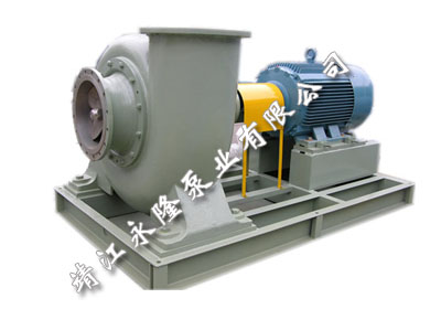
SPP is the horizontal mixed-flow direction with rear withdrawal, a protected shaft sleeve, oil-lubricated bearings and packing or a double mechanical seal. The catalogue explicitly says that the ordered pump name includes the impeller letter: SPP20-25 with impeller A becomes SPP20-25A. A quotation stating only SPP20-25 leaves an important hydraulic configuration unresolved.
At 1450 r/min, the SPP20-25A row gives 530 m³/h, 11.2 m head and 4 m NPSHr. Its listed motor changes from 22 kW for density 1000 kg/m³ to 30 kW for 1350 kg/m³. At 970 r/min, the A row instead gives 350 m³/h and 5 m head, with 7.5 kW and 11 kW motors for those respective densities. Keep the row, impeller letter, speed and density column together; never combine the highest flow with a motor from the slower row.
The impeller-diameter header says metres, although values such as 270 require clarification against a dimensioned drawing. Other rows contain a head value printed as 317 and incomplete motor cells. Do not repair ambiguous catalogue numbers by guessing. The note specifically leaves certain larger-pump motors for agreement at order. Specify absorbed power, motor margin and startup method for the chosen assembly.
The prose claims closed-valve starting and unlimited piping-load tolerance. Use a model-specific startup instruction and allowable nozzle loads instead. Rear withdrawal needs physical clearance, and the oil and seal systems need accessible inspection points. A cast support foot does not approve any pipe load or eliminate the need for supported piping.
FJX selection includes the loop, supports and hot-liquid suction
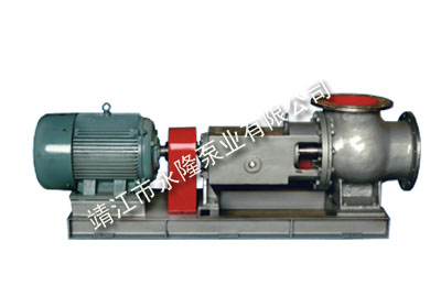
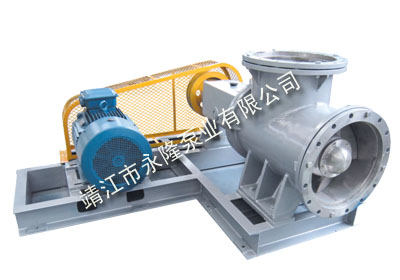
FJX is described for evaporation, concentration and cooling, with ground-foundation or evaporator-mounted support arrangements. The catalogue discusses horizontal and vertical forms, several drives, cast or welded casing construction, and packing or combined mechanical seals. Put the actual support and nozzle arrangement on an approved drawing; these options are not all included in every photographed assembly.
The FJX-450 row publishes ranges of 1290–2858 m³/h, 4–4.8 m head and 730–980 r/min, with separate shaft-power and motor ranges. These columns do not describe one operating point. The page’s general flow maximum is 23000 m³/h, while its FJX-1500 table reaches 24700 m³/h. Ask for a selected curve at the actual recirculation duty rather than deriving a universal maximum from conflicting summaries.
The materials list includes 316/316L, 904L, C-276, Monel, duplex and titanium directions, as well as an unclear 1Ci13Ni9Ti designation. Specify each wetted component’s issued grade and material documentation. The broad 480°C statement and operation at 0.05 MPa absolute pressure are not an approval for the chosen hot liquid, seal or bearing assembly.
For a vacuum evaporator, provide operating absolute pressure, temperature, vapour-pressure data, liquid level and inlet losses. Hydraulic Institute guidance distinguishes available suction head from the pump’s requirement and explains that cavitation effects can occur even with some margin above a published NPSHr. Obtain the selected curve and an appropriate agreed margin. The supplier’s reversal and packing-change descriptions require issued procedures for the exact assembly, rather than an improvised modification or live maintenance instruction.
Read the existing FJX evaporation entry →
LJYA, UHB and CQF have different selection boundaries
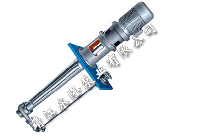
LJYA is a vertical cantilever submerged slurry direction with a semi-open impeller and wear covers. Its text mentions solids below 30% and viscosity below 200 cP, without defining the solids concentration basis. Provide mass or volume fraction, particle distribution, density, abrasion and crystallisation, along with tank depth, lowest liquid level and space to remove the assembly. Ask for the selected construction and operating limits.
UHB is described with UHMWPE wetted construction and K-type dynamic sealing, with open or closed impeller choices. That is a wear/corrosion selection, not a substitute for the clean-liquid magnetic-drive direction. Request the chosen impeller, seal, material and documented compatibility; the claimed five-to-six-times service life is not a measured wear guarantee for your slurry.
The CQF page is headed as a lined magnetic-drive pump but its table names CQB-F models. It also mixes a 120°C introduction with lower temperature entries and an unsupported general self-priming claim. Confirm the exact product and issued filling, lubrication and protection instructions. Do not specify a magnetic-drive pump for the solids duty solely because both pages mention corrosive liquids.
Make alternative quotations comparable at the same duty
Bring the process drawing and liquid specification into the enquiry before choosing the driver or seal. Ask each proposal to identify the complete ordered model, speed, selected working point, materials and package exclusions. Retain revision-controlled curves and drawings so a later substituted impeller, motor or seal is visible.
Agree the tested duty and liquid/test conditions, inspection records, manuals and identified spare parts. Site commissioning should use the supplied alignment, lubrication, seal and starting instructions. The website’s broad quality and lifetime statements do not replace a defined acceptance method, destination service scope or contractual warranty.
Build a structured pump RFQ for comparable quotations →
Chemical transfer
- IH or IHF duty: source/receiving vessel levels, line losses, required flow/head and restart conditions.
- Chemical composition, concentration, contaminants, temperature, density and viscosity.
- Exact lining/alloy and seal, flushing/barrier utilities, leakage requirement and coupling clearance.
SPP or FJX circulation
- Loop drawing, heat exchanger resistance, circulation requirement and normal/abnormal conditions.
- SPP full model with impeller letter, speed and density-specific driver; reconcile ambiguous table units.
- FJX hot-liquid absolute pressure, suction level, supports/nozzle loads, bearing cooling and seal system.
Acceptance and lifecycle
- Issued selected curve, dimensioned drawing, materials, motor schedule and scope/exclusions.
- Agreed hydraulic and configuration checks with traceable results and operating manuals.
- Critical wear/seal/bearing spares, lifting access, destination service and warranty responsibilities.
Submit through KanBeng’s enquiry form with this factory named in your request.