
Select the liquid route and starting arrangement together
Jiangsu Daoer Pump Co., Ltd.
Daoer’s catalogue offers several ways to move liquid from below the pump or circulate it through a process. Compare priming components, immersed construction and complete duty rows before defining the ordered materials, controls and installation.
- Company identity
- 江苏道尔泵业有限公司
- Listed base
- Xinqiao, Jingjiang, Jiangsu
- Selection focus
- Priming · tank installation · process circulation
- Catalogue examples
- ZW · FZBL · WFB · YL · FJX
A surface suction-lift pump and an immersed pump are different proposals
Jiangsu Daoer identifies itself as 江苏道尔泵业有限公司 and lists its base in the Xinqiao industrial area of Jingjiang, Jiangsu. Its catalogue combines several self-priming constructions, fluoroplastic chemical pumps, long-shaft submerged pumps and FJX forced-circulation equipment. Start with the liquid source and the installation arrangement: the same required discharge flow can lead to very different suction, priming and maintenance provisions.
For sewage containing solids or fibres, Daoer’s ZW page describes a recessed impeller arrangement and a passage intended for impurities. It lists a family envelope of 8–800 m³/h and 15–80 m head, with 25–300 mm nominal size. Those independent ranges are a catalogue boundary, not a promise that the largest flow and head occur together. Specify particle size, fibre content and concentration, then request the curve and passage dimensions of the proposed ZW size.
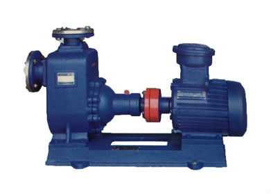
Match the product route to the liquid and the source level
Daoer offers distinct routes rather than a single universal self-priming package. Compare what must happen before liquid reaches the impeller, what is immersed in the source, and which components require access for service.
| Catalogue route | Decision it addresses | Order-specific information |
|---|---|---|
| ZW self-priming sewage | Surface-mounted transfer of solids/fibre-bearing liquid | Passage dimensions, suction layout, priming instructions and solids duty curve |
| FZBL fluoroplastic self-priming | Corrosive-liquid transfer with the pump above the source | Full chemistry, first-fill procedure, retained liquid and seal construction |
| WFB / TXW / TZFB | Different automatic or assisted priming arrangements | Air-control or vacuum equipment, starting sequence, retained prime and guaranteed priming conditions |
| YL / long-shaft submerged | Pump intake within a tank or sump | Minimum/maximum levels, immersed length, column support and removal route |
| FJX forced circulation | Large-flow process circulation with relatively low differential head | Process pressure, temperature, loop losses, drive and seal auxiliaries |
Self-priming does not remove the need to define first start and restart
The FZBL page describes a metal-supported fluoroplastic liquid end and an external bellows mechanical seal. It requires filling before first use and describes subsequent starting using retained liquid. Its stated suction height depends on liquid density. Include the cold first start, restart after shutdown and restart after draining in the enquiry; a proposal that works with a filled chamber may behave differently after maintenance or loss of prime.
Daoer’s TXW description combines a main pump with a vacuum priming tank or vacuum pump, and says the tank and suction pipe normally remain filled. WFB instead describes an electric air-control valve and a centrifugal sealing arrangement. TZFB is presented as another construction with its own air-extraction device. Ask each proposal to identify the actual components and interlocks rather than treating these names as interchangeable suction-lift ratings.
Give the lowest liquid level, site elevation, liquid temperature, suction-pipe diameter and length, bends, valves and inlet arrangement. Specify a permitted priming time under these stated conditions and a response to failed prime. Review inlet pressure and NPSH as well as static lift; neither an air-extraction device nor the family name establishes permission to run the selected pump dry.
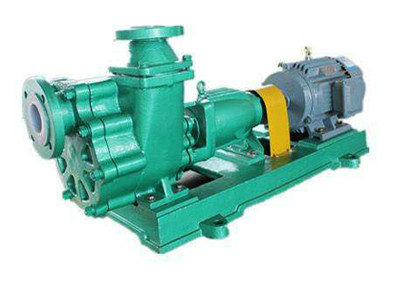
Use complete performance rows instead of mixing catalogue maxima
The WFB table includes speed, flow, head, matched power, nominal connections and an allowable suction-depth column. The following examples retain flow and head from the same displayed row. They are useful for screening a proposal; the operating curve, liquid properties and agreed material/configuration still govern selection.
WFB is listed in stainless steel, reinforced polypropylene and cast-steel constructions. State the material and ordered category explicitly. Include the electric air-control valve and its control logic in the supply boundary, and ask for operating and stopped-pump sealing instructions. A catalogue statement about an explosion-proof option does not establish certification of every pump, motor or complete assembly.
| WFB example | Flow / head from one row | Speed | Matched power | Listed inlet / outlet |
|---|---|---|---|---|
| 25WFB-A | 3.6 m³/h / 25 m | 2,900 rpm | 3 kW | 25 / 20 mm |
| 40WFB-A1 | 13.5 m³/h / 18 m | 2,900 rpm | 3 kW | 40 / 32 mm |
| 50WFB-AD | 6.3 m³/h / 10 m | 1,450 rpm | 1.5 kW | 50 / 40 mm |
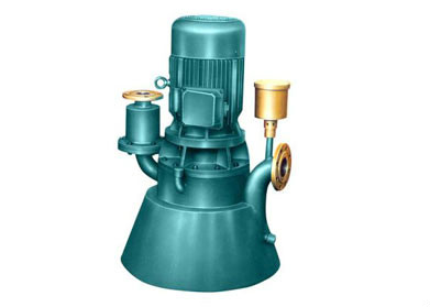
For YL and long-shaft submerged pumps, start with the tank drawing
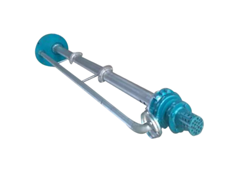
Daoer has separate catalogue entries for YL vertical multistage long-shaft pumps and long-shaft submerged pumps. Their illustrations show different column and liquid-end arrangements. Choose between them using the liquid duty and complete installation drawing; a long shaft alone does not identify stage count, bearing lubrication or permitted immersion.
Send the tank depth and opening, support elevation, minimum and maximum liquid levels, sediment conditions, nozzle orientation and required discharge head. Request immersed length, wetted materials, bearing/support arrangement and any flushing or lubrication services. The minimum running level must support the proposed intake arrangement, not simply match the bottom of the tank.
Check removal before ordering: a replacement column or shaft may need vertical clearance or an agreed dismantling sequence. Specify lifting points, available crane/door clearance, isolation and drainage. For an existing installation, provide the old assembly drawing and dimensions rather than assuming a new long-shaft catalogue illustration will fit.
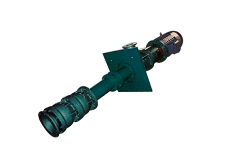
FJX selection needs both loop resistance and process pressure
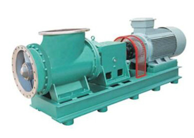
The FJX entry concerns forced circulation and lists several seal alternatives, including packing and mechanical-seal arrangements. One clearly paired catalogue entry is FJX450: 2,000 m³/h, 4 m head, 980 rpm and 55 kW matched power. Other size rows contain ranges across configurations, so they should be followed by a selected speed and curve rather than treated as one performance point.
In an evaporator or concentrator loop, differential head describes the circulation resistance; it does not define the casing’s permitted absolute process pressure. Supply vessel pressure or vacuum, liquid temperature and density, crystallisation/solids conditions, required circulation flow and calculated loop losses. Ask the quotation to identify the driver/coupling arrangement and seal-support services for the actual process.
Agree shutdown and restart handling for the process liquid, access to the liquid end, and the cooling or barrier requirements of the proposed seal. Avoid selecting the largest catalogue flow “for safety” without checking the resulting operating region and the process-loop requirement.
Specify the full liquid end, not only “fluoroplastic”
FZBL describes fluoroplastic-covered components and different mechanical-seal face choices; the FSB entry describes moulded fluoroplastic wetted parts. Define the chemical name and concentration, mixtures, temperature range, solids and cleaning liquid. Confirm every wetted component: casing/liner, impeller, seal faces, bellows or elastomers, gaskets and any auxiliary piping.
For the FZBL solids-bearing option, the page mentions silicon-carbide face pairing. Confirm particle size and loading with that exact seal arrangement rather than assigning it to every FZBL pump. Obtain a material schedule and duty-specific temperature limits; broad statements about resistance to all acids or concentrations cannot replace a compatibility review.
If the liquid changes between production, washing and shutdown, include all three conditions. A configuration selected for the normal liquid may need a different seal or operating procedure during cleaning. Tie replacement seal and liner parts to the approved drawing and order designation.
Make priming and hydraulic acceptance two separate checks
For a suction-lift proposal, agree the test liquid, starting fill state, source level, suction-pipe arrangement and time-to-delivery requirement. For hydraulic acceptance, agree the selected speed, flow/head points, motor loading and applicable test basis. Record whether results use water or the actual process liquid and which corrections are required.
Before blaming the pump for low delivery, compare the installed suction arrangement, air ingress, liquid level, rotation, density and viscosity with the approved duty. A suction-side joint can admit air without showing an outward liquid leak. Also identify pressure measurement locations so pipe losses or elevation changes are not mistaken for pump differential head.
Request a general-arrangement drawing, operating/priming sequence, wiring and interlock details for supplied auxiliaries, material schedule, selected curve, test record and drawing-linked spare parts. Define who supplies field piping, supports, level signals and commissioning. Catalogue photos and application labels do not establish a completed reference project or witnessed factory test.
Send a source-level and starting-condition brief
Prepare the enquiry around one actual installation. Identify whether you need sewage transfer, corrosive-liquid suction lift, an immersed tank pump or process circulation, and ask for a configuration-specific proposal.
Review the existing Daoer ZW catalogue record →
Prepare a structured pump-system enquiry →
Liquid and process
- Chemical composition and concentration; density, viscosity and cold/normal/hot temperatures.
- Solids size and loading, fibres, sediment or crystallisation; cleaning and shutdown liquids.
- Minimum/normal/maximum flow and differential head; vessel pressure or vacuum where applicable.
Suction and installation
- Lowest/highest liquid levels, site elevation and complete suction-piping sketch.
- First-start fill state, restart after drainage, required priming time and failed-prime response.
- Tank opening, immersed length, support/nozzle positions and lifting/removal clearance for long-shaft proposals.
Order and verification
- Exact series/size, material and seal schedule; motor supply and hazardous-area requirements if applicable.
- Supplied air-control/vacuum devices, signals, interlocks, auxiliary services and site-work boundary.
- Selected curve, paired test points, priming demonstration, drawings, instructions and spare-parts identification.
Submit through KanBeng’s enquiry form with this factory named in your request.