
Select the water-transfer duty before choosing the drive and discharge layout
Yancheng Yuanquan Pump Co., Ltd.
Yancheng Yuanquan’s catalogue is useful for irrigation and drainage buyers comparing HW mixed-flow arrangements, ZLB axial-flow pumps and engine-driven assemblies. The decisive documents are the selected pump curve, seasonal water levels and installation drawing. An HW size alone does not define the speed, head or complete pump set.
- Company identity
- 盐城市源泉泵业有限公司
- Listed base
- Xinyang economic area, Yancheng, Jiangsu
- Core catalogue
- HW/HBC mixed flow · ZLB axial flow
- Order interfaces
- Water levels · discharge layout · drive
A water-transfer supplier with more than one installation arrangement
The company introduction identifies 盐城市源泉泵业有限公司 in Yancheng. Its principal catalogue directions are 100–650 HW/HBC mixed-flow pumps and 250–800 ZLB axial-flow pumps, alongside self-priming, centrifugal, vacuum-priming and engine-driven equipment. These are catalogue identifiers and size directions, not a shared flow range or a guarantee that each option is available in a current quotation.
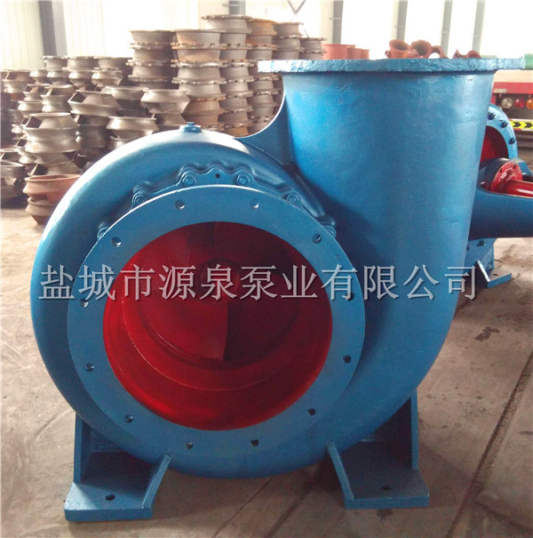
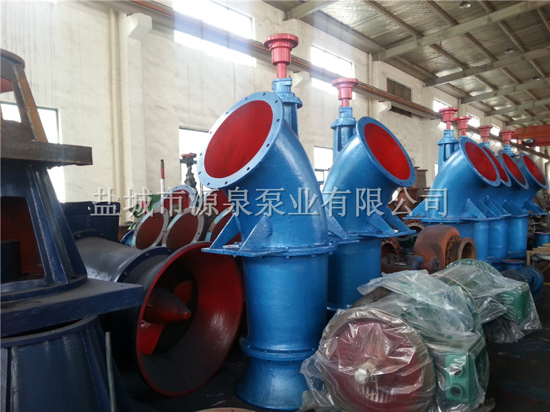
The existing public HW entry here remains the place to compare that family. The original photographs distinguish an upper-discharge casing, belt-pulley configurations, vertical arrangements and engine-driven assemblies. For a replacement, send the present installation drawing and nameplate as well as the desired duty: matching the nominal size is insufficient if the outlet, drive or maintenance access changes.
The company introduction describes irrigation, drainage, municipal water transfer and industrial circulation. Its historical export and ministry-designation statements are not used here as current approvals or verified customer references. Define the actual destination support, spares and acceptance obligations in the purchase documents.
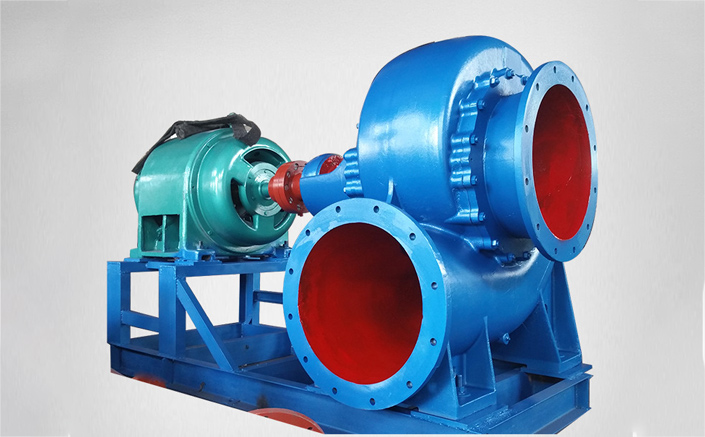
The same HW designation can have two different hydraulic selections
The HBC/HW performance table contains separate speed blocks. For 150HW-5S at 1450 r/min, the middle flow/head pair is 180 m³/h at 5 m; the row also prints 3 kW shaft power and a matching-power entry of 5 HP / 4 kW. At 1850 r/min, the corresponding middle pair is 230 m³/h at 8.2 m, with 6.3 kW shaft power and 12 HP / 7.5 kW matching power. The shaft-power and driver columns describe different quantities.
Each speed block contains several paired flow/head points. The table does not say that every point has the same absorbed power, so request the issued complete curve and driver loading across the intended operating range. Do not combine a flow from the faster block with the head or motor from the slower block.
The catalogue also offers individual HW and ZLB curve images. Some older scans are too small for a dependable numerical reading, and isolated table entries have inconsistent flow units or unexpected trends. The examples below retain clear original pairs; unresolved rows should be clarified through an issued selection sheet rather than silently corrected. A model suffix or family maximum is not an acceptance result.
| 150HW-5S table block | Middle flow / head pair | Printed shaft / matching power | Printed critical NPSH |
|---|---|---|---|
| 1450 r/min | 180 m³/h / 5 m | 3 kW / 5 HP–4 kW | 3 m |
| 1850 r/min | 230 m³/h / 8.2 m | 6.3 kW / 12 HP–7.5 kW | 3.5 m |
Discharge orientation and maintenance access belong in the quotation
The 650HW-5S product description identifies a horizontal, single-stage, single-suction mixed-flow construction with front and rear access. It describes clean water or liquids with similar physical and chemical properties, with liquid temperature no higher than 50°C for that direction. That condition does not establish compatibility with abrasive slurry or corrosive process liquid.
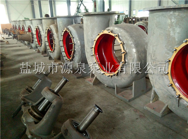
The model explanation identifies 650 as the inlet/outlet diameter in millimetres, HW as a horizontal volute mixed-flow construction, 5 as design head in metres and S as its structural form. A design-head identifier does not replace a curve at the chosen speed. Other catalogue photographs distinguish upper and lower discharge configurations; confirm the nozzle orientation, elevations, flange details, footprint and space to withdraw components.
The operating direction is described from the pump inlet, with a specific 650HW-7S exception. Put the exact direction and viewing convention on the selected assembly drawing rather than assuming every HW rotates alike. The published photographs of casings and assemblies help discuss configuration; they do not demonstrate current inventory, production capacity or a witnessed hydraulic test.
Belt speed and engine power must be specified together
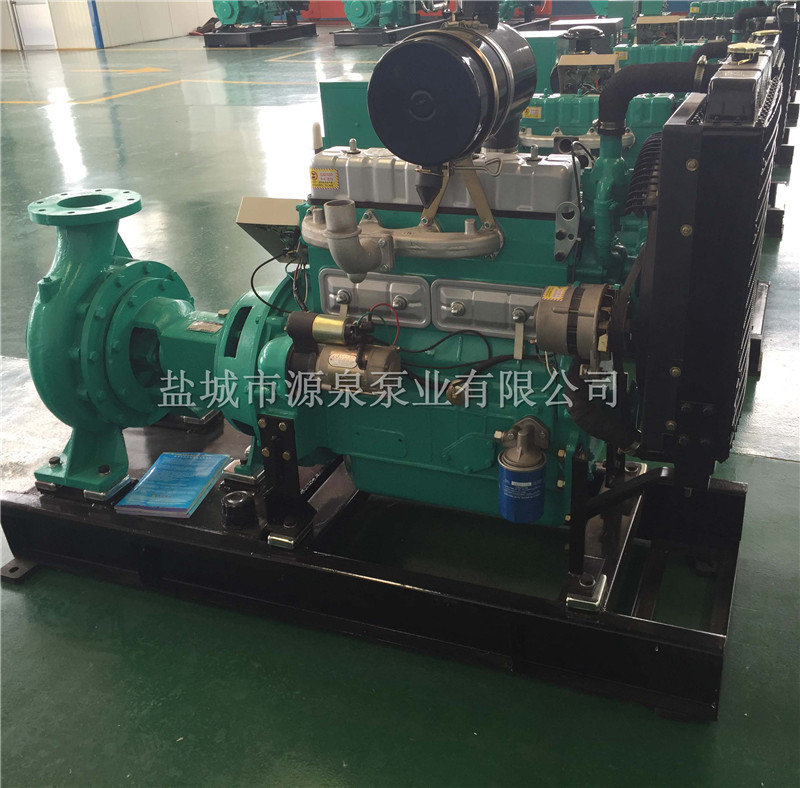
The HW-S instructions describe direct and belt transmission, using electric motors or diesel engines. They explicitly ask the buyer to state driver power and speed so the coupling or pulley can be determined. If the engine runs at a different speed from the selected pump curve, require the actual transmission ratio, shaft speed, alignment arrangement and guards.
For an engine-driven irrigation set, define what is included: pump, engine, coupling or belt drive, base, cooling, exhaust, fuel arrangement, starting equipment and controls. Provide the intended site altitude, temperature and operating hours for the driver selection. The catalogue’s engine-assembly photograph proves a listed configuration; it does not establish an engine make, fuel-consumption figure or continuous-power rating for every set.
The diesel product text includes broader industry examples and other named manufacturers. Those examples are not adopted as Yuanquan projects, fire-pump certification, hazardous-area approval or automatic-start capability. An independent engine-driven water pump still needs project-specific hydraulic selection, operating instructions and a defined supply boundary.
A vacuum primer does not remove the suction and intake constraints
The HW-S installation guidance discusses placing the pump close to the water source, limiting unnecessary inlet length, keeping inlet flow reasonably uniform and preventing air leaks. It also describes screening vegetation and debris. Send the lowest and highest seasonal water levels, inlet dimensions, line losses and expected debris to the supplier before finalising the installation elevation.
Hydraulic Institute guidance distinguishes available site suction head from the pump requirement and explains that some cavitation effects can occur even above a published NPSH requirement. Establish an appropriate margin at the worst intended liquid level and temperature. An old catalogue’s intake-distance multiples should not be treated as a universal design for every river, canal or sump.
Yuanquan’s SZG page describes a water-ring vacuum direction for pump priming. Its prose gives 8 litres/second at 520 mmHg, but the table’s model column unexpectedly says 100HW-8S. Confirm the actual primer identity, gas conditions, working-water supply and vacuum reference before adopting that rating. A primer evacuates air; it does not establish permissible suction lift or approve dry running of the main water pump.
The ZLB catalogue contains a separate 20ZLB-100 blade-angle curve and photographs of vertical assemblies. An axial-flow proposal needs the selected blade setting, shaft arrangement, intake geometry and installation drawing. Do not transfer an HW curve, inlet requirement or driver schedule to the axial-flow configuration.
A nominal pump size is not a sufficient spare-part reference
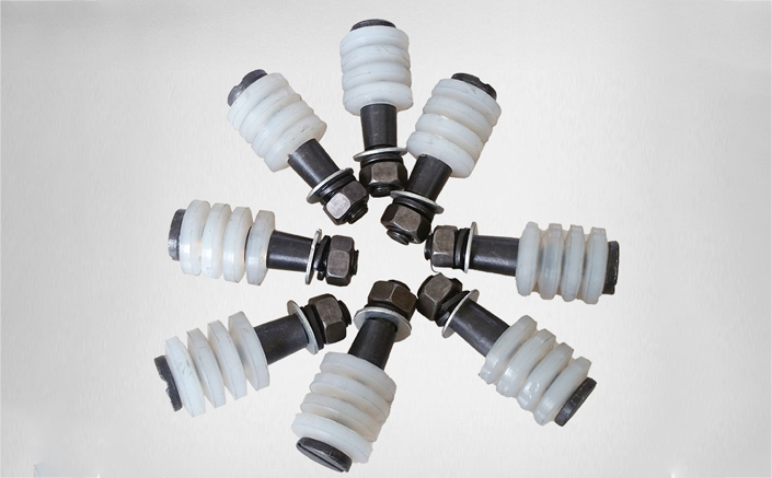
The spare-parts pages show coupling pins for 10-, 12- and 14-inch directions, impellers, flap valves, bottom valves and pipe fittings. For a repair order, supply the complete pump model, existing serial/nameplate information, drawing reference, actual dimensions and material or elastomer requirements. A coupling pin must fit the installed coupling, not merely a similarly named pump.
The company introduction offers spare-parts and service commitments. Translate these into the destination, duration, response arrangements, parts list and warranty terms of the quotation. For acceptance, the HW-S description refers to GB/T 13008 and JB/T 6667. The official national-standard catalogue identifies GB/T 13008-2010 as the technical specification for mixed and axial-flow pumps; a published standard reference is not evidence that this particular order has passed a test. Agree the applicable edition and supplied records.
Send the duty, layout and acceptance requirements as one brief
Ask the proposal to identify the full pump designation, selected speed, paired duty point and offered drive. Retain the curve and dimensional drawing with their revisions so changes to outlet orientation, pulley ratio or motor remain visible. Compare complete assemblies at the same site conditions, rather than only comparing nominal HW sizes.
Hydraulic and seasonal conditions
- Required flow and total head, daily operating range and seasonal intake/discharge water levels.
- Liquid temperature, sediment and vegetation, intake geometry, pipe losses and suction assessment.
- Selected HW curve and speed, or ZLB blade setting and installation requirements.
Assembly and installation
- Upper/lower discharge, nozzle elevations, footprint, maintenance clearance and lifting access.
- Electric supply or engine duty, driver power/speed, belt ratio or coupling, guarding and control scope.
- Whether the offer includes primer, screens, valves, fittings, base and installation auxiliaries.
Test and lifecycle documents
- Agreed standards/editions, duty-point acceptance, test conditions and traceable results.
- Assembly drawing, installation and startup instructions, exact spare-parts references.
- Destination service, parts availability, exclusions, lead time and contractual warranty.
Submit through KanBeng’s enquiry form with this factory named in your request.